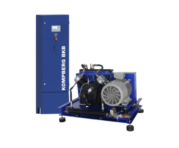
Booster compressor, KOMPBERG® BKB
Booster compressor 22 KW (KOMPBERG® BKB)
Booster compressor DescriptionThe compressor is intended for compressing air only. Its use to compress other gases requires prior agreement with machine manufacturer or vendor. Such agreement must be made in writing. The compressor may not be used for any purpose other than specified.
Top
KOMPBERG®️ BKB22 Booster Compressor
Net €14,290.00
€17,005.10*
Booster Compressor KOMPBERG®️ BKB22
Booster Compressor KOMPBERG®️ BKB Description
The compressor is intended for compressing air only. Its use to compress other gases requires prior agreement with machine manufacturer or vendor. Such agreement must be made in writing. The compressor may not be used for any purpose other than specified.
Booster Compressor KOMPBERG® BKB Technical Description
Applications
The KOMPBERG®️ series booster compressors are intended for boosting air pressure from 1-1.3 MPa (KOMPBERG®️ BKB22) on the suction side, to 2.5-4.0 MPa on the pressure side. The booster is provided with an oil filter and end cooler.
Main components
The booster compressor comprises an oil piston compressor with “V” cylinder arrangement at 90° angle. The compressor is driven by an electric motor with a belt transmission. A common frame supports the compressor, motor and air end cooler with fans and filters.
The compressor
It is a one-stage, two-cylinder, one-sided compressor, with a "V" cylinder configuration and a 90 bifurcation angle.
A compressor carter with a tunnel structure is made as a cast iron cast. The lower part of the crankcase is at the same time an oil sump in which the oil suction filter is mounted. The oil filter is mounted on the oil pump.
Two cylinders with working valves are attached to the compressor's crankcase. The working valves are pressed against the heads of the head with adjustment screws through special pressure sleeves. In order to ensure more efficient heat dissipation, the cylinders and heads are suitably ribbed.
Crankshaft, cast of nodular cast iron with increased impact strength, is supported by two rolling bearings. On the one hand, the crankshaft has a conical tip for seating the pulley, while a gear-driven oil pump is driven from the other end of the shaft.
Two connecting rods with two-part thin-walled bushes are mounted on the surface hardened crank shaft.
Both cylinders on the intake are connected by a common intake manifold, and on the discharge by an air cooler.
Electric motor
The booster compressor is driven by a squirrel-cage, AC electric motor. The motor is designed for an intermittent run, for maximum 20 starts per hour. The compressor is driven by the motor via a belt transmission.
End cooler
The cooler in the KOMPBERG®️ boosters is made of vertical ribbed steel tubes connected with horizontal collectors at the ends. The cooler has welded construction. In the upper cooler collectors, valves for draining condensate and a relief solenoid valve are provided. Air circulation in both solutions is forced by a fan driven by an electric motor.
Booster compressor frame
The KOMPBERG®️ BKB22 booster frame, on which the motor and compressor are supported, is made of plate and seated on four shock absorbers.
Downloads
Technical Data Booster Compressor KOMPBERG®️ BKB22 , PDF( Size: 107 KB )
Booster microprocessor controller , PDF( Size: 650 KB )
Electric box, PDF( Size: 225 KB )
Exploded view draw BKB 22 , PDF( Size: 2 MB )
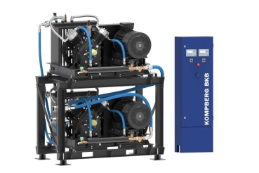
KOMPBERG®️ BKB22 TWIN Booster Compressor
Net €27,340.00
€32,534.60*
Booster Compressor 22 TWIN Description
The compressor is intended for compressing air only. Its use to compress other gases requires prior agreement with machine manufacturer or vendor. Such agreement must be made in writing. The compressor may not be used for any purpose other than specified.
Technical Description Booster Compressor 22 TWIN
Applications
The KOMPBERG®️ series booster compressors are intended for boosting air pressure from 1.0-1.3 MPa (KOMPBERG®️ BKB22 TWIN) on the suction side, to 2.5-4.0 MPa on the pressure side. The booster is provided with an oil filter and end cooler.
Main components
The booster compressor comprises an oil piston compressor with “V” cylinder arrangement at 90° angle. The compressor is driven by an electric motor with a belt transmission. A common frame supports the compressor, motor and air end cooler with fans and filters.
The compressor
It is a single-stage compressor with two cylinders, one-side action, with “V” cylinder arrangement at 90° angle.
The compressor has a tunelled iron cast crankcase. The crankcase bottom serves also as an oil sump with the oil suction filter built in. The oil filter is installed in the oil pump.
Two cylinders with valves are mounted to the crankcase. The valves are held in place in their seats in the head with adjustment bolts through special thrust sleeves. The cylinders have special ribs to ensure efficient heat removal.
The crankshaft forged of increased impact-resistant steel is supported on two rolling bearings. On one side, the crankshaft is provided with a cone end for pulley mounting, whereas the other end drives the oil gear pump.
On a skin-hardened crank pin of the shaft, two connecting rods with thin-wall double-split bearing bushings are mounted.
There are no separate heads in the compressor, as the cylinder and head is a one-component iron cast. Both cylinders are linked with a common suction collector, at the inlet side, and with the air end cooler, at the outlet side.
Electric motor
The booster compressor is driven by a squirrel-cage, AC electric motor. The motor is designed for an intermittent run, for maximum 20 starts per hour. The compressor is driven by the motor via a belt transmission.
End cooler
The cooler in the KOMPBERG®️ boosters is made of vertical ribbed steel tubes connected with horizontal collectors at the ends. The cooler has welded construction. In the upper cooler collectors, valves for draining condensate and a relief solenoid valve are provided. Air circulation in both solutions is forced by a fan driven by an electric motor.
Booster compressor frame
The KOMPBERG®️ BKB22 TWIN booster frame, on which the motor and compressor are supported, is made of plate and seated on four shock absorbers.
Downloads
Technical Data Booster Compressor KOMPBERG®️ TWIN , PDF( Size: 107 KB )
Booster microprocessor controller , PDF( Size: 650 KB )
Master controller RC-LTDW , PDF( Size: 560 KB )
Schematic diagram KOMPBERG®️ BKB22 TWIN , PDF( Size: 492 KB )
Electric box, PDF( Size: 225 KB )
Operating and maintenance manual KOMPBERG®️ TWIN , PDF( Size: 1.4 MB )
Exploded view draw BKB 22 , PDF( Size: 2 MB )
Technical data Booster compressor KOMPBERG® BKB
| Model | Capacity [m3/h] Suction pressure |
Compressed air connection | Electric power | Compressor rotational speed |
Dimension | Weight | |
| 10 bar | 13 bar | [kW] | [Rpm] | [mm] | [kg] | ||
| BKB 22 | 300 | 330 | G 3/4 | 22 | 900 | 1335 x 875 x 850 | 495 |
| BKB 22 Twin | 600 | 660 | G 1 1/4 | 2 x 22 | 900 | 1607x851x1955 278x500x1600 |
1208 |
While operating the compressor:
- Observe the instructions provided in the Manual and Warranty Book.
- Technical and operating checks should be performed by the manufacturer or authorised service, using the manufacturer’s parts and consumables.
- During the warranty period, use only manufacturer’s parts and consumables.
Basic requirements for safe transport and positioning of the boosters
In addition to the general H&S and Technical Supervision regulations, the following rules must be observed:- Use only H&S compliant and approved by the Technical Supervision lifting equipment to lift the compressor. Fix in place all rotating or loose parts of the machine before lifting it. It is strictly forbidden to stand in the hazardous range of the lift operation. Machine movement can be accelerated or slowed down only within applicable limits.
- The compressor is transported on wooden pallets which should be secured against movement during transport. Fasten the compressor frame with cargo straps to appropriate holders on the vehicle platform to prevent it from sliding or overturning.
- All screw and pipe connections should be of appropriate size and designed for a given operating pressure.
- The compressor is not designed to operate outdoors.
- The compressor should be installed in a closed room, in cool and clean ambient air. Never block air flow to and from the room. Ensure sufficient flow of cooling air and extraction of heated air out of the room.
- The air sucked in should contain no vapours or flammable gases, e.g. paint thinners, that might cause internal fire.
- There can be no objects close to the air inlet that could be sucked in with a jet of air.
- The pressure conduit connecting the compressor with the compressed air line should allow free expansion due to generated heat. It may not touch hot objects or combustible materials.


