Product information "Inline Flow meter VA 520"
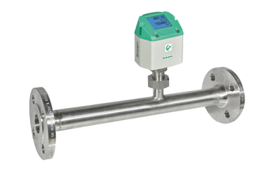
Inline Flow meter VA 520
By installing a flow meter in a compressed air system, operators can monitor and track the usage of compressed air, identify fluctuations in flow rates, and detect abnormalities that may indicate leaks or other issues. This information can help optimize system performance, improve energy efficiency, and reduce operational costs.
Flow meters for compressed air and gas come in various types, including thermal mass flow meters, vortex flow meters, and differential pressure flow meters. Each type has its own set of features and capabilities, allowing operators to choose the most suitable option based on their specific monitoring needs and system requirements.
In summary, using a flow meter for compressed air and gas as part of a compressed air monitoring system can provide valuable insights into system performance, energy consumption, and overall efficiency, helping operators make informed decisions to optimize their operations and reduce costs.
Available items for Inline Flow meter VA 520 sensors
| Product | Description | Order No. |
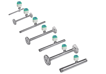
| VA 520 flow meter with integrated DN 25 measuring section with flange | 0695 2523 | |
| VA 520 flow meter with integrated DN 50 measuring section with flange | 0695 2525 | |
| VA 520 flow meter with integrated DN 65 measuring section with flange | 0695 2527 | |
| VA 520 flow meter with integrated DN 80 measuring section with flange | 0695 2528 |
Application-technological features of the flow meters VA 520
- Diggital interfaces such as Modbus-RTU, Ethernet (PoE) and M-Bus enable agement systems, building managment systems, PLC, ...
- Easy and affordable installation
- Units freely selectable via keys on the display m3/h, m3/min, l/min, l/s, kg/h, kg/min, kg/s, cfm
- Compressed air counter up to 1,999,999,999 m3 can be reset to "zero" via keypad
- Analog output 4...20 mA, pluse output (electrically isolated)
- High measuring accuracy even in the lower measuring range (ideal for leakage measurement)
- Negligibly small loss of pressure
- Calorimetric measuring principle, no additional pressure and temperature measurement necessary , no mechanically moved parts
- Comprehensive diagnostic functions can be read out on the display or remote access via Modbus-RTU such as exceeding max./min values °C, calibration cycle, error codes, serial number. All parameters can be read out and changed via Modbus
Technical Data VA 520
| Parameters | m3/h, l/min (1000 mbar, 20 °C) in case of compressed air or Nm3/h, Nl/min (1013 mbar, 0 °C) in case of gases |
| Units adjustable via keys at display | m3/h, m3/min, l/min, l/s, ft/min, cfm, m/s, kg/h, kg/min, g/s, lb/min, lb/h |
| Sensor | Thermal mass flow sensor |
| Measured medium | Air, gases |
| Gas types are adjustable over CS service software or CS data logger | Air, nitrogen, argon, CO2, oxygen |
| Measuring range | See Measuring range table |
| Accuracy (m.v: of meas. value) (f.s.: of full scale) | ±1.5% of m.v. ± 0.3% of f.s. on request: ±1% of m.v. ± 0.3% of f.s. |
| Operating temperature | -30... 80°C |
| Operating pressure | -1...16 bar optionally up to PN 40 |
| Digital output | RS 485 interface, (Modbus-RTU), optional: Ethernet interface PoE, M-Bus |
| Analogue output | 4...20 mA for m3/h or l/min |
| Pluse output | 1 pulse per m3 or per litre electrically isolated. Pluse weight can be set on the display. Alternatively, the pluse output can be used as an alarm relay |
| Supply | 18...36 VDC, 5 W |
| Burden | < 500 Ω |
| Housing | Polycarbonate (IP 65) |
| Measuring section | Stainless steel, 1.4404 or 1.4571 |
| Process connection | Flange (in acc. with DIN EN 1092-1 or ANSI 150 lbs or ANSI 300 lbs) |
| Mounting position | any |
| Flow measuring ranges VA 520 (max version 185 m/s) for compressed air (ISO 1217: 1000 mbar, 20°C) | Flange DIN EN 1092-1 | ||||||||||
| Measuring section | Outer pipe mm | Inner pipe | Measuring range full scales | L | L1 | H | H1 | ØD | ØK | n x ØL | |
| mm | m3/h | (cfm) | mm | mm | mm | mm | mm | mm | |||
| DN 25 | 33.7 | 27.3 | 290 | 170 | 475 | 275 | 223.2 | 165.7 | 115 | 85 | 4 x 14 |
| DN 50 | 60.3 | 53.1 | 1195 | 700 | 475* | 275 | 248.2 | 165.7 | 165 | 125 | 4 x 18 |
| DN 65 | 76.1 | 68.9 | 2050 | 1205 | 475* | 275 | 268.2 | 175.7 | 185 | 145 | 8 x 18 |
| DN 80 | 88.9 | 80.9 | 2840 | 1670 | 475* | 275 | 275.7 | 175.7 | 200 | 160 | 8 x 18 |
| * Attention: shortened inlet section. Please observe the recommended minimum inlet section (length = 15 x inner diameter) on site. | |||||||||||
Monitoring the compressed air with a flow meter
A flow meter for compressed air and gas can be considered a type of compressed air monitoring equipment. Flow meters are used to measure the flow rate of compressed air or gas moving through a system, providing valuable data on the volume of air being consumed, the efficiency of the system, and potential leaks or inefficiencies.By installing a flow meter in a compressed air system, operators can monitor and track the usage of compressed air, identify fluctuations in flow rates, and detect abnormalities that may indicate leaks or other issues. This information can help optimize system performance, improve energy efficiency, and reduce operational costs.
Flow meters for compressed air and gas come in various types, including thermal mass flow meters, vortex flow meters, and differential pressure flow meters. Each type has its own set of features and capabilities, allowing operators to choose the most suitable option based on their specific monitoring needs and system requirements.
In summary, using a flow meter for compressed air and gas as part of a compressed air monitoring system can provide valuable insights into system performance, energy consumption, and overall efficiency, helping operators make informed decisions to optimize their operations and reduce costs.
Login


